[ { "uid": "link_contact", "linkName": "Contact", "url": "/us/contact##wago-support-contact-anchor", "target": "_self", "classAttributes": "phone" } ]
On this page:
[{"term":"Libraries_BA","id":0,"type":"QUICKLINKS"},{"term":"Instructions","id":1,"type":"QUICKLINKS"},{"term":"WAGO-I/O-PRO","id":2,"type":"QUICKLINKS"},{"term":"Building","id":3,"type":"QUICKLINKS"},{"term":"221","id":4,"type":"QUICKLINKS"}]
WAGO Electronic Circuit Breakers (ECBs) with a high switch-on capacity is combined with an electronic relay.

Electronic Circuit Breakers (ECBs)

A high switch-on capacity is combined with an electronic relay. WAGO’s space-saving ECBs come into play when the focus is on both safety and a superior price-performance ratio.

WAGOs full line of Single and Multi-Channel ECBs have a lot to offer:

  • They offer reliable protection against overload and short circuit.
  • They also enable activation of high-capacity loads of 50,000 microfarads and higher – without the need to increase the nominal current setting.
  • 1-, 2-, 4- and 8-channel models with 0.5 to 16A current ratings offer you the flexibility you need for setting the nominal current to suit your individual application.
  • Single Channel ECBs 6mm wide and Multi-Channel ECBs starting at 32mm wide allow for high channel density in a small space.
  • Some devices are also available with active current limitation, preventing the power supply unit from overloading during a short circuit.

New Product Feature

787-3861: Next Generation WAGO Single-Channel Electronic Circuit Breakers

WAGOs next generation 24 VDC, 1-channel ECBs improve operations and offer a significant cost savings for customers. The 787-3861 family of products no longer has a hard to open cover to access the manual reset wheel, instead offering an indented button to be operated with a tool. The devices include LED status indicators to identify device status as well as S1 input and S2 output to monitor and control the device remotely. New in the 787-3861 family is the ability to configure the S2 output on ALL variants in to report 7 different states including triggered or manually switched off, and early load warnings. On adjustable units, the current limit is able to be set via discrete setting wheel instead of a sequence of inputs through the manual input wheel, making it much easier to set and identify current setting when first glancing at the device. In addition, 4 A and below variants now include NEC Class 2 output options as well as a new 0.5 A to 4 A configurable NEC Class 2 version.

Advantages:

  • 24 VDC; six fixed and two adjustable rated current versions from 0.5 A to 8 A
  • Easy to identify current setting on adjustable versions
  • 6mm slimline design
  • Easy Jumpering to 857 and 2857 series devices with same terminal layout
  • High switching capacity: > 50,000 μF for non-NEC Class 2 devices
  • S1 Input and Configurable S2 Output for easy remote monitoring and control
  • Approvals: CE, UL 61010, UL 2367, and UL 1310 NEC Class 2 Versions
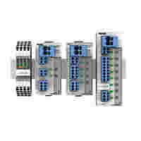
2-, 4- and 8-Channel ECBs

WAGO’s space-saving ECBs provide reliable protection with a superior price/performance ratio. They offer both outstanding features and reliable protection against overload and short circuits. With a maximum width of 45 mm (1.772 inches), these ECBs feature high channel density to save space in the control cabinet.

Advantages:

  • Two-, four- and eight-channel protective switch with currents adjustable from 0.5 to 12 A
  • High switch-on capacity: > 50,000 µF
  • Communication capability: remote monitoring and reset
  • Optional active current limitation
  • Approvals: CE, UL 60950, UL 2367, GL

787-2861: Single-Channel Electronic Circuit Breakers (ECBs)

The new modules are just 6 mm (0.236 inch) wide, making them the slimmest ECBs currently available. They are approximately 66 % smaller than miniature circuit breakers, saving even more space, particularly when used in control cabinets. These ECBs enable high-capacity loads greater than 50,000 microfarads to be switched on – helping you reduce false tripping due to inrush currents.

Advantages:

  • 24 VDC, seven versions available for rated currents of 0.5 A to 8 A
  • With devices color coded according to nominal current
  • An extremely slimline design
  • Switch-on capacity: >50,000 µF
  • Wide surrounding air temperature range: −25 … +70°C (−13 … +158°F)
  • Resetting, on/off switching directly on the module or remotely via digital input signal
  • Triggered signal output can also be combined as a group signal for up to 30 devices
  • Approvals: CE, UL 61010, UL 2367

Why Secondary-Side Fuse Protection?

On the secondary side, switched-mode power supplies provide DC voltage to control circuit loads (e.g., controllers, operating panels, displays and auxiliary relays). These control circuits also call for wiring protection and if the load has no protective unit of its own, device protection as well. Furthermore, Machinery Directive EN 60204 requires detecting hazardous ground faults in control circuits and switching them off within five seconds.

The overcurrent protection in primary switched-mode power supplies reacts very quickly to overcurrents on the output side. Selective protection of individual current paths in the secondary circuit via fuses or conventional circuit breakers is often ineffective if the power supply cannot deliver a brief overcurrent.

grafik-sekundaerseitige-absicherung_2000x2000px.jpg

What Types of Fuse Protection Are There?

Thermal

Possible applications:

  • Low-voltage, high-power and DP fuses
  • High overcurrents required for fast tripping

Explanation:

  • In the example: ten-fold overcurrent (related to fuse nominal current): Tripping within a range of 30 ms (best case) or 200 ms (worst case)
  • Only two-fold overcurrent: tripping within a range of 2 s (best case) or >100 s (worst case).
grafik-thermisch_2000x2000px.jpg

Thermal and Magnetic

Possible applications:

  • Found in circuit breakers or motor protection switches
  • High overcurrents required for fast tripping

Explanation:

  • In the example: three- to five-fold overcurrent for B-characteristic and AC operation, additional safety factor: 1.2 or 1.5
  • Thus, in the worst case scenario, a tripping current of 7.5 times the nominal current is necessary.

grafik-thermisch-und-magnetisch_2000x2000px.jpg

Electronic

Possible applications:

  • Precision setting options
  • Reaction within a short time – even with low overcurrents
  • Protection of long cable runs and small cross sections possible

Explanation:
ECBs ensure reliable protection, even at low overcurrents and with long cable lengths.

grafik-elektronisch_2000x2000px.jpg

How Does an ECB Function?

The ECB checks whether the output current is greater than the nominal current. As soon as the output current exceeds the nominal current, the output is electronically switched off by a semiconductor switch. Trip time depends on the magnitude of the overcurrent. The measurement of the output current, the processing and calculation of the tripping time and the actuation of the semiconductor switch are performed by a microprocessor that monitors one or more output channels. The corresponding tripping times can be found in the graph on the right.

grafik-funktion_2000x2000px.jpg

ECB Advantages

  • Switch off secondary-side overcurrents and short circuits – even with long cable runs and small conductor cross sections – with precision, speed and repeatability
  • Selectivity, especially with ECBs with active current limitation
  • Remote operation via digital input and output
  • Fast and reliable communication via IO-Link protocol, signal contact, potential-free signal or Manchester protocol
  • Advantageous installation size and width, for example, eight output channels in just 42 mm (1.653 inch), which saves more than 70 % of installation space compared to miniature circuit breakers
  • Nominal current assignable for each channel
  • Satisfy EN 60204-1 requirements for dependably switching off ground faults after five seconds
grafik-elektronische-absicherung_2000x2000px.jpg